Many SmallSat missions require propulsion.
The primary propulsion system trade is electric propulsion vs chemical propulsion.
Electric Propulsion
High specific impulse, but low thrust, and power required.
Chemical Propulsion
High thrust, and little/no power required, but has low specific impulse.
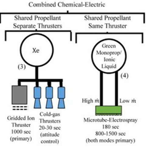
Our Solution: Dual-Mode Propulsion
- Combines chemical and electric propulsion modes
- Fills niche allowing high-impulse missions with maneuverability
- EP use cases: orbit raising, orbit maintenance, end-of-life disposal
- CP use cases: responsive reconnaissance, collision avoidance
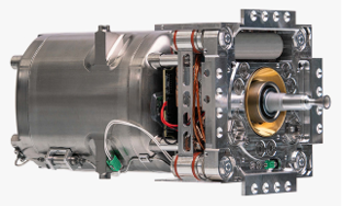
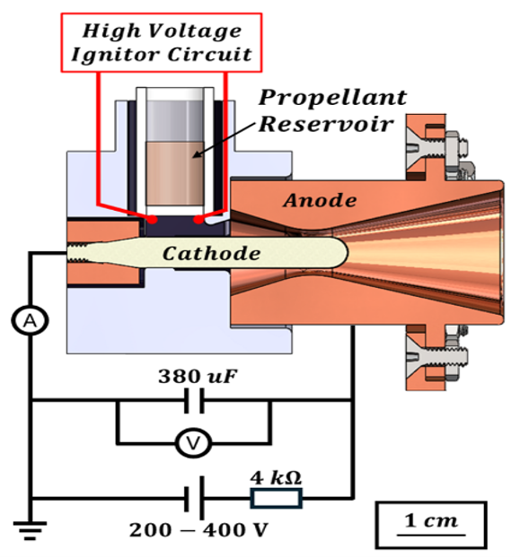
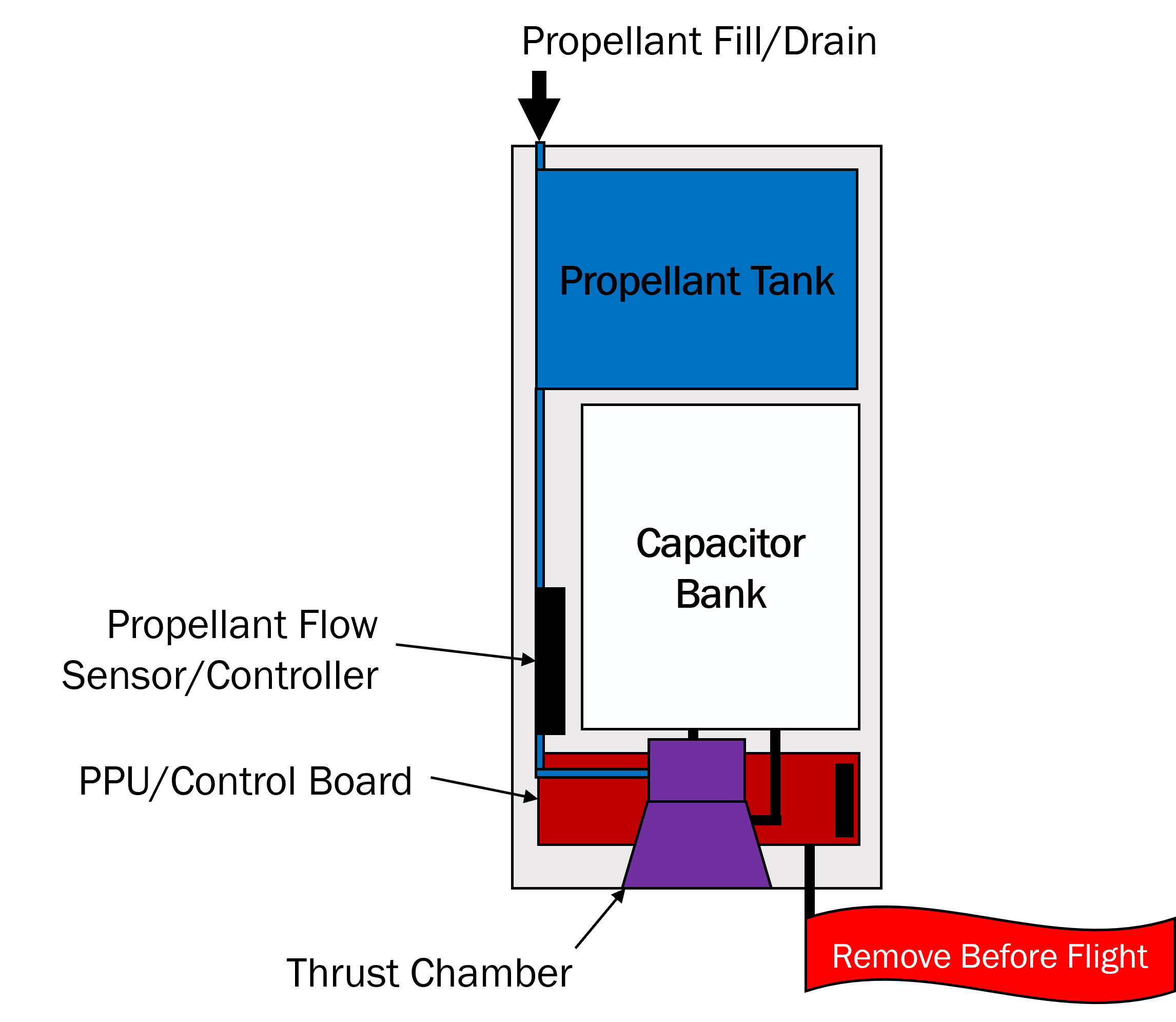
Pulsed Magnetoplasmadynamic Thruster
- Coaxial geometry reduces ohmic heating
- Fritted glass disc provides passive and reliable propellant feed
- Low cathode erosion rate
- Liquid propellant provides high mass utilization efficiency
- Ideal for dual-mode adaptation using ASCENT propellant
The thruster operates via a high-current pulse between anode and cathode, accelerating plasma through Lorentz force.
ASCENT: Advanced Spacecraft Energetic Non-Toxic Propellant
- Developed by AFRL as a safer hydrazine alternative
- Higher density and lower toxicity (only respirator and gloves required)
- Higher theoretical specific impulse for CP
- Low vapor pressure and freezing point
- Promising for new dual-mode propulsion applications
Experiment Description
The PMPD thruster and propellant system are tested via successive orbit raising and lowering maneuvers. Data collected from various sensors determines performance metrics and monitors propulsion system health.
Expected performance (500 g propellant, 10 kg spacecraft) will guide the next stage of experimental validation.
Thruster Testing
The PMPD thruster undergoes performance testing to characterize mass consumption and thrust per pulse. Tests include measuring mass loss before and after firing, thrust via pendulum stand, and tracking pulse count.
Current estimates have error due to evaporation losses and chamber coupling. Future testing will refine these results and enhance performance characterization to meet mission goals.